

1. What is planer?
Planner is a machine tool which removes the metal from the workpiece by the reciprocating action of the workpiece. In this machine, the tool is not moved.
2. What is drilling?
Drilling is the process of producing a hole on the workpiece using a rotating drill.
3. What are the nomenclatures of drill?
1.Body
2.Shank
3.Neck
4.Point
5.Land
4. Name the driving mechanisms which are used in slotter.
i) WhitWorth Mechanism
ii) Variable speed motor drive
iii) Hydraulic drive
5. What are the differences between shaper and planner?
| S.No | Planner | Shaper |
| 1. | Workpiece reciprocates and tool is stationary | Tool reciprocates and the work is stationary |
| 2. | Suitable for machining large and heavy work piece | Suitable for machining medium and small piece |
| 3. | More accurate operation | Less accurate operation |
| 4. | Heavy cut cannot be given | Heavy cut can be given |
6. What are the different types of quick return mechanisms used in planer?
i) Open and Cross belt drive
ii) Hydraulic Drive
iii) Electrical Drive
7. What are the various types of drilling machine?
i) Plain Type
ii) Semiuniversal Type
iii) Universal Type
8. Define boring?
The process of enlarging the already drilled hole is known as boring.
9. Explain the construction and working of radial drilling machine.

Radial drilling machine is used for drilling the medium and large size workpiece. A special part Radial arm is mounted on the column.The radial arm can be moved up and down and radially on the column and clamped. This machine has the following parts.
1.Base
Base is the rectangular shaped large casting part. Table and column are fitted on the base.’T’ slots or made on the base for holding and clamping the large size worlpiece.
2.Column
This cylindrical part is mounted on the base.The column supports the radial arm, drill head and motor. The column must have super fine finishing for easy movement of radial arm. An elevating screw is fitted in the column for moving up and down of the radial arm.
3.Table
This fitted on the base.’T’ slots are made on the table to hold the workpiece.The surface of the column is finished well for moving the radial arm up and down on the cylindrical surface of the column. An elevating screw is situated in the side of the column for moving the radial arm up and down on the column.
4.Drill Head
Drill head is fitted on the radial arm. A separate motor is provided to the drill head. Drill head can be moved by hand or by motor. The deal is held in the drill head.
5.Spindle Head and Feed Mechanism
Spindle is operated by gearbox. Feed can be given by manually or automatically. Radial drilling machine is classified on the basis of movement of the radial arm and tool head.
10. With a neat sketch explain the open and cross belt drive mechanism in planner.

The figure shows the line diagram of open and cross belt drive. In this method, an electric motor drives a counter shaft. Two wide faced pulleys of same diameter or inserted in the counter shaft. Open belt is connected with one pulley and cross belt is connected with another pulley.
The driving shaft is placed below the table. You’re driving pinion his fitter at the one end of the shaft. The another end of the shaft carries a set of two small pulleys and two large pulleys. One of the smaller pulleys and one of the larger pulleys are keyed with the shaft. They are called fast pulleys. The other two pulleys rotate freely on the shaft. They are called loose pulleys. The speed of the driving shaft can be reduced by a speed reduction gear box. The driving pinion meshes with the rack provided at the bottom of the table. The table reciprocates while the pinion rotates. The position of the open belt and cross belt is changed by a belt shifter.
During the return stroke, cross belt connects the large loose pulley. Open belt connects the smaller fast pulley. Now the drive is transmitted to the main shaft through the smaller fast pulley. So, the table moves faster.
At the end of the return stroke, the trip dog pushes the belt shifter. Both the belts are shifted to the right. Now the cross belt connects the larger fast pulley and the open belt connects the smaller loose pulley. So the drive is transmitted to the main shaft through the cross belt on the larger fast pulley. Now the direction of rotation of main shaft is reversed. Because of the larger diameter of the pulley, the speed of main shaft is reduced. So, the table moves slowly during the cutting stroke.
At the end of the cutting stroke , both the belts are shifted to the previous position by another trip dog. This the return stroke are obtained successively.
11. Explain whitworth quick return mechanism with a neat sketch.
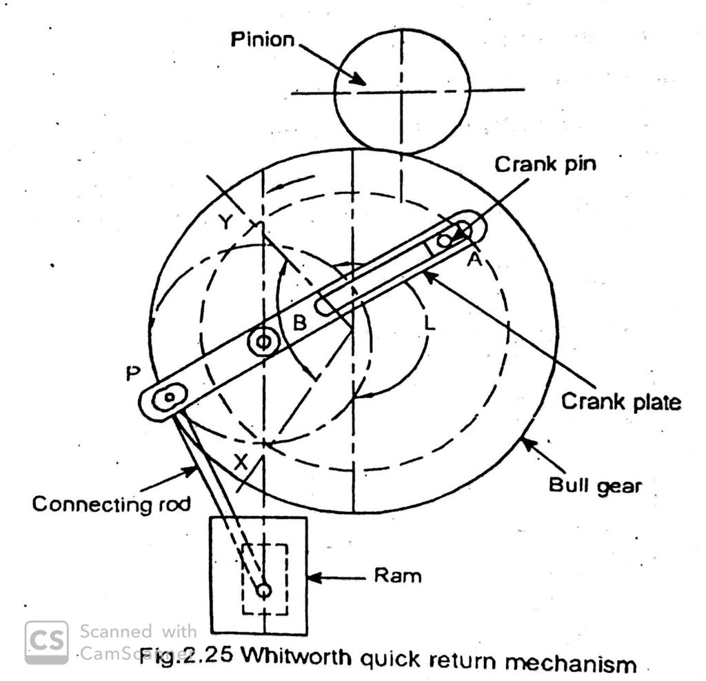
Electric motor shaft rotates the pinion. The pinion makes the bull gear to rotate. A crankpin is in the bull gear. A sliding block is sliding on the crank pin and also slides in the slot of crank plate. This crank plate is pivoted from the points eccentrically. One end of the connecting rod is connected with pin (P) and the other end is connected at the end of ram (M).
When the pinion rotates the crank pin with bull gear also rotates. At the same time the sliding block slides on the
slot provided on the crank plate. Due to this, the ram reciprocates through the connecting rod. When the pin A is in X, the ram is in the forward stroke. At that time the bull gear rotates at angle α in anticlockwis direction. Return stroke takes place from the point Y to X at the angle β in the same direction. Here, angle β is smaller than angle α. So, the time taken to complete the return stroke is reduced.
. m = Cutting time/Return time = angle α /angle β
 important questions and answer")
")
")

