

1.What is resistance?
Resistance (R)
The opposition by a substance to the flow of electric current is called resistance.
It is represented by ‘R’. The unit of resistance is ohm(Ω)
2. Define magnetic flux density.
It is usually denoted by the letter b and it’s unit is Tesla (Weber/sq.meter). If a flux of ‘ϕ’ Weber is passing through an area of A square metre , then the flux density B is given by
[latex]B=\frac{ϕ}{A} (web/sqm)[/latex]
3. What is called time period?
The time taken to complete one cycle of an alternating quantity is called its time period. It is represented by T
4. Define peak value.
The maximum +ive or -ive value of an alternating quantity is called amplitude or peak value.
5. Define MMF.
The force which establish the magnetic flux in a magnetic circuit is called magneto motive force. It corresponds to electro motive force.(E.M.F) in a electric circuit.
F=NI ampere turns
6. Define reluctance.
Reluctance is the property of a material which opposes the establishment of magnetic flux in it. It is the resistance offered to the passage of magnetic flux through a material. It is similar to resistance in an electric circuit.
then, Reluctance = mmf/ϕ
So the unit of Reluctance is AT/Wb.
7. What is RMS value?
The value of steady current which has caused the same heat as that of alternating current is known as Root Mean Sqare value or effective value.
8. State the losses in transformer.
The power losses in a transformer are of two types namely
1.Core losses (or) iron losses
2.Copper losses
PART-C
9. Write the principle and operation of DC motor.
D.C motor converts Electrical energy into mechanical energy. Whenever a current carrying conductor is placed in a magnetic field, a mechincal force is produced on the conductor. D.C motor works on the above principle.
The magnitude of the force is given by, F = BLI Newton
Where
F = .Force produced on the conductor in Newton
B = Magnetic flux density in Web/m2
L= The length of conductor in the magnetic field
I = The current flowing through the conductor in ampere
To understand the principle of operations of D.C motor. Let us consider a two pole motor.
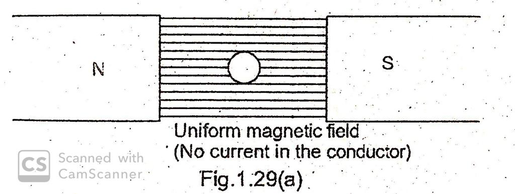
Fig 1.29(a) shows a uniform magnetic field in which a straight Conductor carrying no current is placed. The direction of magnetic flux line is from North to South pole.
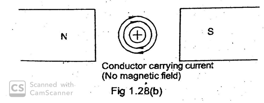
Now assume there is no exciting current flow through the field winding and D.C current is sent through the conductor. Let the conductor carry the current away from the observer. It produces a magnetic flux lines around that in clockwise direction as shown in Fig.1.29(b). There is no movement of the conductor during the above two conditions.
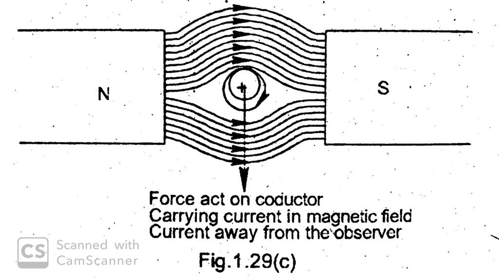
Fig.1 .29(c) the current carrying conductor is placed in the magnetic field. The field due to the current in the conductor aids the mainfield above the conductor, but opposes the mainfield below the conductor. Hence the flux strengthens above the Conductor and weakens below the conductor. it is found that a force acts on the conductor, trying to push the conductor downwards as shown by the arrow (The Conductor is pushed from high flux density to low flux density).
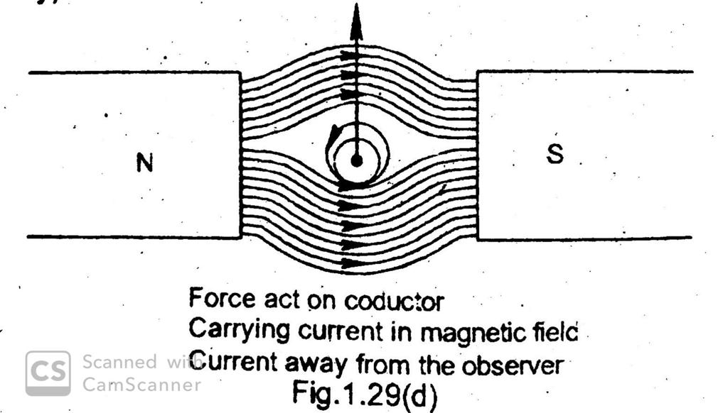
If the current in the conductor is reversed current towards the observer (.) the strengthening of flux line occurs below the conductor and the conductor will be pushed upward as shown in fig.1.29(d).
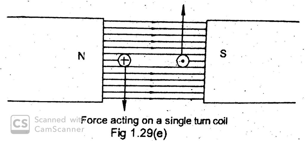
Now consider a single turn coil carrying current as shown in fig.I.29(e), the coil side ‘A’ will be forced to move downwards, whereas the coil side ‘ET will be forced to move upwards. The forces acting on the coil sides ‘A’ and T3′ will :be of same magnitude, but their direction is opposite to one another. As the coil wound -on the armature core, which is supported by the bearings, the armature will now rotate. The direction of rotation is found out by Fleming’s left hand rule. TYPES OF MOTORS Depending upon the way in which the field winding is Connected with armature winding the D.C motors are classified as
10. Explain three point starter with neat sketch.
THREE POINT STARTER
This starter is used to start D.C shunt motor and compound motor. The circuit diagram of three point starter is shown in fig.1.33. Since the motor is connected to supply terminals through three terminals L, A and F, it is called three point starter.
In this starter, the resistor elements are mounted behind an insulation board. The tapping points of starting resistance are brought out to a number of studs. The handle of the starter is fixed to a point so as to be moved over the studs against a spring tension.
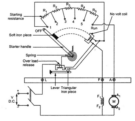
When the starter handle is moved to the first stud, a reduced voltage is applied to the armature, due to drop in the resistor elements. Hence the starting current is limited to safe value. At the same time full voltage is applied across the field, and this produces normal flux. When the starter handle is moved towards right, the resistor elements are cut out one by one and the voltage applied to the armature increases step by step. When all resistances are cut out, the handle is in on position, Now full voltage is applied across the Armature terminals. A soft iron piece is attached to the handle. Now the handle is attracted by the No volt release coil (electromagnet).
No voltage release
It consists of an electromagnet (NVR). It .is connected in series with the shunt field circuit and hence it carries shunt field current. So this is energised. It holds the handle in ‘ON’ position. In the case of failure of supply or the voltage is very low, the no volt coil gets de-energised and handle flies back to ‘off’ position.
Overload release
This also consists of an electromagnet. The electromagnet is energised by the line current. When the load on the motor is increased, the magnetising force produced by this coil is sufficient to lift the movable iron. The movable iron in turn short circuits the ternimals of the No volt release. Hence the no volt coil is handle returns de-energised and the starter handle returns to ‘OFF’ position, Thus overload rease protects the motor against over loads.
Demerits
A motor can be run for a higher speed than normal speed by reducing the field current. The reduced field current may not produce enough magnetic force to hold the handle in ‘ON’ position.. So the handle returns to the ‘OFF’ position. This is the disadvantage of three point starter. It is pliminated in four point starter.
11. Explain single phase transformer with neat sketch.
SINGLE PHASE TRANSFORMER
Introduction
The device which is used to stepping up or stepping down of voltages is known as transformer. They can step up or step down alternating voltage only.
PRINCIPLE OF OPERATION
A transformer is a static electric machine which transfers electrical energy from one circuit to another circuit without change in its frequency. Due to electromagnetic induction principle, the transfer of energy takes place. It consists of three essential parts. (1) Primary winding (2) Secondary winding (3) Laminated iron core. The A.C supply given to the winding is known as Primary winding. The winding from which electric supply is taken is called secondary winding. The connection diagram Is shown in fig.2.8.
The two windings are wound over an iron core. The iron core is laminated to reduce eddy current Loss. The transformer works on the principle of mutual induction. When an A.C supply is given to primary winding an alternating flux is set up in the core. This alternating flux cuts both the primary and the secondary winding. According to Faraday’s mutual induction principle an emf is induced in the secondary winding. If we connect a load to the secondary winding, current will flow through the load. In this way electrical energy is transferred from the primary circuit to the secondary circuit. The emf induced in the windings depends upon the number of turns of the windings. If the number of turns in the secondary winding is more than that of the primary winding, the emf induced in the secondary winding will be higher than the voltage applied to the primary winding. This type of transformers is said to be step up transformers.
If the number of turns in the secondary winding is less than that of the primary winding, the emf induced in the secondary winding will be less than the voltage applied to the primary winding. This type of transformer is said to be step down transformer.


